As mentioned in a previous post my copy of the Sjöberg vise made many years ago, has a problem. The stabilizer bars on either side of the vise screw are only loosely held in the holes in the baltic birch of the fixed jaw. In fact the holes are about 1/16" too large for the 1/2" round stabilizer bars.
The simplest solution is making a bushing to fit in the holes with a hole that more tightly fits the stabilizer bars, 0.500" diameter. The first task was disassembling the vise. Pins holding the stabilizer bars in the moving jaw were removed. The jaw could then be completely unscrewed from the base. The fixed jaw with the too large holes was attached to the front of the base with six machine screws, all easily removed.


The moving jaw was held in a vise attached to the drill press table. A 3/4" Forstner bit was held in the chuck and the table was adjusted until the marks made from pressing the bit against the wood were evenly spaced on all sides of the old hole. The drilling was done in 1/2" increments, providing the drill bit some time to cool down after each plunge. When the drill bit depth reached the limit of the drill press, the second hole was drilled.

The holes drilled measured 0.752" in diameter and 1.56" deep. Brass bushings were planned to fill these holes. Two 1.5" lengths were cut from 3/4" brass round bar with a hacksaw. Both ends were faced in the Sherline lathe. The part was center drilled and drilled up to 3/8" from 0.180". A boring bar was used to enlarge this hole to a sliding fit with the bars.

In order to increase the holding power of the glue used to hold the bushings in the holes in the Baltic birch plywood, scratches were made along the length of the bushings. Two part epoxy was made up and spread in the newly enlarged holes and the bushings were tapped into place. A bit of excess glue was wiped out with a shop towel.


The glue needs 24 hours for a full cure, but in the meantime the fixed vise jaw was reinstalled on the base with the six socket head cap screws.

The vise was put back together to test the fit of the stabilizer bars and they didn't go in past the moving jaw. the slots are too shallow as there is no longer any play to help them fit! The photo below shows how this lack of depth was managed before, but just at the fixed jaw end of the vise. Quite the budgie job! Who works like this?

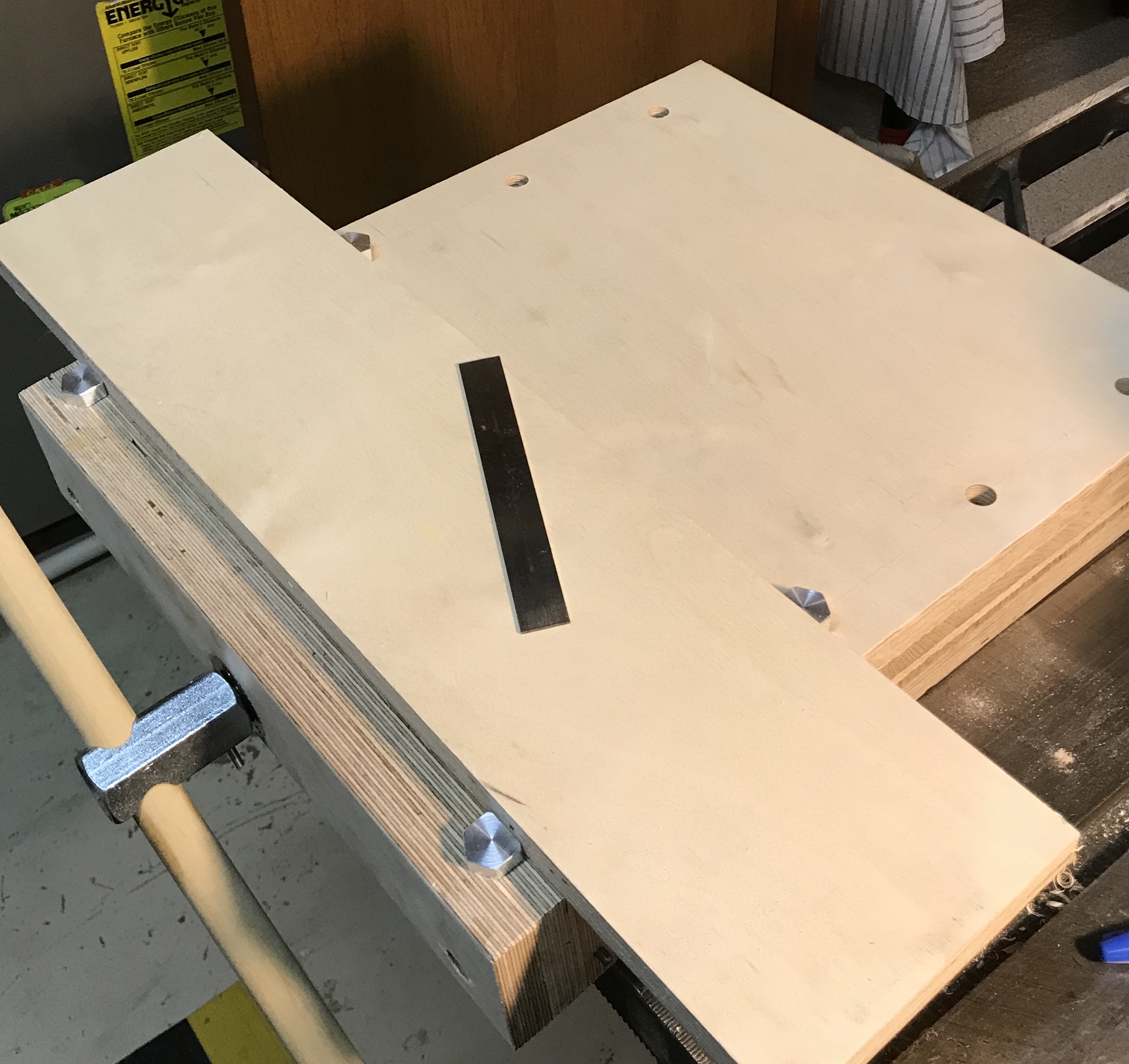
After taking the vise apart, the bottom of the vise was clamped to the table saw extension and a fence was attached 3" from the near edge of the dado. (The router selected has a 3 1/4" base radius.) The bottom was routed out with a 3/8" straight bit, from 7/8" deep to 1". The base was unclamped and the fence was installed 3" from the opposite dado and once again the dado was deepened.

The twelve screws were reinstalled to test out the deeper slot and it was a no go! The dadoes also need to be widened. The vise was disassembled, clamped, fence clamped, and routed, removing 1/16" of material on the near side of the dado. The fence was moved so the same amount of wood was removed from the opposite side. This process was repeated on the other dado. The photo below shows 1/8" wider and 1/8" deeper dado.

The same was repeated on the other side and then the vise was put back together. The previous problem of the moving jaw sagging leading to poor clamping has been fixed. But ... one of the stabilizer bars is tight and as the vise is opened and closed this side of the vise doesn't move and needs constant tapping to keep it tracking with its opposite partner. It is too close to a good sliding fit! OY!!!
In an effort to fix the problem, sanding was undertaken. A scrap of 1/2" square cherry was chucked in a four jaw chuck in the lathe. 2 1/2" of the length were reduced to 3/8". A 2" strip of carpet tape, 1 3/16" wide was wrapped around the rod, followed by a matching strip of 320 grit sandpaper. In retrospect coarser sandpaper should have been used, but I was worried about a rough finish. After ten minutes of sanding the inner bore with the sanding dowel held in a cordless drill, the diameter had increased to 0.506", similar to the other bushing. When inserted, the shaft seemed to have the same amount of movement as the freer floating shaft. The bore was blown out with the Wolfbox Superpower Turbo Fan MegaFlow 100™.
I can't describe how happy I am with this compressed air blower. I have never had compressed air in the shop, relying on blowing and canned air. The latter is a pain as it is limited in how much air can be ejected prior to getting too cold to function. The Wolfbox fan is high intensity compressed air. It was compared to other similar devices on Project Farm and was the standout. If you don't have compressed air in your shop, buy one!
The Sjöberg vise worked no better than before reaming the bushing. The left support shaft slides freely during closing the vise, but the recalcitrant shaft is still recalcitrant. Both shafts were oiled with 3-in-1 with no positive impact on vise performance. The vise certainly clamps more securely, but getting to that point is a pain. Checking the problematic shaft with a square is the next thing to try.
Maybe I should have purchased a Sjöberg vise. I certainly have not saved much, considering the time spent to make this tool functional! Though I haven't factored the lessons learned into the equation.
Removed the floating jaw and checked the two stabilizer bars for squareness, with respect to the jaw. Both had enough movement in all directions that squareness did not matter. I found the jaw easy to move out by just keeping a bit of pressure on the recalcitrant side. The same was seen with putting the jaw back on the vise. A bit of pressure and the jaw closed fairly uneventfully.
Since the vise is mostly functioning an upgrade was in order. To use the vise as is, the vise has to be clamped to a workbench. With clamps covering the front two corners, the vise is somewhat impaired when tackling longer stock. Two boards were glued to the back of the vise. One oak cutoff was cut to fit the width of the vise and glued to the back of the back side. A second oak cutoff was about 4" longer than the width of the vise and was glued to the back of the fixed jaw. The extensions will allow clamping without compromising the vise's utility.

